BLOG POST
Does Tracking Error Actually Matter?
Why Every “Zero Compromise” Tonearm Involves a Trade-Off
Few phrases appear more often in Hi-Fi marketing than “no compromise.” It is commonly attached to tonearms designed for zero tracking error and perfect groove tangency. It’s certainly an appealing prospect, but it is incomplete, and often, ‘no compromise’ in one specific design issue simply creates problems elsewhere.
We’ve been designing tonearms for more than 30 years, with many lessons learned the hard way during development. Almost every design solution has a form of compromise. The knack is to compromise as little as possible and to sacrifice the least amount of rigidity and pivot freedom. Tonearm designs that attempt zero tracking error are to be applauded for their innovative engineering, but often this pursuit comes with greater compromises in the fundamentals than conventional pivoted tonearms. The following is an account of where those compromises arise and why they cannot be avoided.
What Is Tracking Error?
Tracking error is the lateral angular deviation between the stylus and a straight line running along the radius of the record groove. To understand why it occurs, it helps to consider how a record is produced.
When a record is cut, the cutterhead of the lathe travels along a lead screw or linear rail in a straight line across the lacquer, moving from the outer edge towards the centre while cutting the groove by vibrating horizontally and vertically in response to an analogue stereo input. A pressing is subsequently made from that lacquer. The essential point here is that the cutting head creating the groove moves in a straight line.
Most tonearms do not. Setting aside linear and tangential trackers, at least 95% of arms on the market are pivoted. Because pivoted arms rotate around a fixed point, the cartridge and its stylus move across the record in an arc. An arc cannot remain perfectly perpendicular to a groove that was cut in a straight line, so for the majority of the record, the stylus sits at a slight angle to the groove rather than at the ideal right angle.
The consequence is audible (though admittedly often less audible than other issues). When the stylus is not square to the groove, its contact points on the groove walls shift, introducing minute phase errors between the channels. In practice, this presents as a slight loss of clarity and reduced separation between instruments.
Overhang, Null Points and the Offset Angle
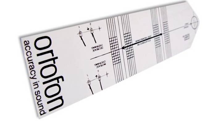
The objective for most arms, then, is to make the best of an arc. This is why cartridge alignment geometries exist – to try and get the least distortion possible from an arcing motion. The foundational work here is attributed to Wilson, who established that by extending the stylus slightly beyond the spindle you could lower distortion. This distance is known as overhang, and allows the arc to be made perfectly tangent to the groove at two points on the record. These are the null points: the two radii at which tracking error falls to zero.
Outside of those two null points, some error remains. The established alignment geometries are Baerwald (also termed Löfgren A), Löfgren B, and Stevenson, the latter used by both Rega and Technics. These main geometries differ principally in the positions of those two null points. Placing them further inward (Stevenson) improves inner-groove performance at the end of a record’s side; placing them further outward (Baerwald and Löfgren) favours the outer and middle grooves. None of these geometries removes tracking error; each redistributes it.
A further requirement follows. For the stylus to sit genuinely square to the groove at the null points, the cartridge must be angled inward relative to the arm tube. This is the offset angle, typically around 23 degrees on a nine-inch arm. Two relationships are worth noting: a longer arm requires less overhang and a smaller offset angle, because its wider arc more closely approximates a straight line; these both reduce the magnitude of the next issue to consider…
Skating Force
It is widely assumed that a pivoted arm tends to swing outward as the stylus tracks towards the centre. The opposite is actually true.
Because the cartridge is angled with an offset in order to reduce tracking error, the frictional force exerted on the stylus by the record does not act in line with the arm tube. It acts on one side, so that the arm tube functions as a lever, drawing the assembly inward toward the spindle. This inward force is known as skating force, and if uncorrected, it loads the inner groove wall more heavily than the outer.
The correction is anti-skate, or side bias: a controlled outward force, normally applied at the rear of the arm, that opposes the skating force. When correctly set, the benefits are audible. An easy practical method to set anti-skate is to select a recording with a centrally placed vocal and adjust the bias until the voice is positioned centrally; when the setting is incorrect, the image shifts to one side. Correct adjustment also noticeably improves instrument separation and focus.
Why Anti-Skate Is Not a Complete Solution
In theory, anti-skate would cancel the skating force entirely. In practice, it cannot, because the skating force is not constant.
It varies with the alignment geometry as the stylus moves between the null points and, more significantly, with the recorded material. The drag experienced during a heavily modulated passage, such as an orchestral crescendo, is considerably greater than during a quiet solo passage. As drag increases, the skating force increases, while the anti-skate setting remains fixed. The correction is therefore static, applied to a variable force.
The variation across the record, however, is less extreme than might be expected because record production already compensates to a degree. The inner grooves contain more modulation within a shorter length, which raises friction there and broadly offsets the lower groove velocity. Nonetheless, the variation is never fully eliminated, which is why anti-skate should be regarded as the most effective available measure rather than a definitive solution.
Tracking Error or Side Force: Which Is More Important?
This is the more in-depth question, and several designers have approached it from an unconventional standpoint.
The ViV Laboratory Rigid Float, designed by Koichiro Akimoto, prioritises reducing side force over minimising angular tracking error. The arm is unconventionally short at 7″ (although it also comes in 9″ and 13″ variants); it is underhung from the turntable’s spindle, with no overhang and no offset angle, so that it is perfectly tangent at only one single point. Interestingly, the lack of an offset at the headshell results in substantially lower side force than with a conventional arm. The trade-off, however, involves some pretty big compromises: geometric tracking error across the remainder of the record is significantly higher. It has attracted a committed following, which underlines the central point: both factors matter and affect performance. Emphasising one compromises the other.
Designs That Aim to Eliminate Tracking Error
For those seeking to eliminate angular error entirely, several approaches exist, each with its own cost.
The simplest is a pivoting headshell, such as the NASOTEC unit, which mounts onto a standard bayonet headshell connector. The headshell pivots freely, letting groove drag draw it into alignment at every point, while a pair of lightly tensioned springs restrains it. The method reduces tracking error but also reduces rigidity, and rigidity is what holds the cartridge stable. Adding springs in such a crucial area of the tonearm sacrifices the arm’s inertial stability and rigidity.
A more refined solution is the Thales arm, which uses two arm tubes and a cam mechanism to continuously adjust the headshell angle, maintaining tangency throughout the arc while providing considerably greater rigidity than a pivoting headshell. The geometry is complex, which is one reason such arms are typically high-end, but this arrangement also limits the tube thickness you can use, introduces a second resonant structure, and again sacrifices ultimate rigidity at the tonearms headshell.
Tangential trackers, including designs by Reed and Schröder, move the arm’s base, guided by a system of levers, so that the stylus remains square to the groove. These are accomplished and necessarily costly, since the additional pivots must be made rigid and free of resonance. The complication with tangential tracking tonearms is whether the friction of the groove is able to pull the entire arm assembly back and forth – which isn’t hard to imagine when it’s generally accepted that this happens in almost all horizontal bearing types with most tonearms (excluding the Supatrac). Fixed-base pivoted arms might employ angled pivots, lower the pivot point as close to the playing surface as possible, or add mass and other stabilising techniques to their horizontal pivot. The base of a tangential tracker, however, has to move in order to achieve tangency, which leaves it more open to back and forth motion than any other type of tonearm. Some manufacturers can constrain the moving base adequately; others less so.
The linear, or parallel, tracker represents the theoretical ideal. Mounted on a rail, it follows the cutting lathe’s straight-line path directly. In practice, it introduces its own difficulties: air-bearing designs require pumps that must often be sited remotely for acceptable quietness, mounting can be awkward, and the principal challenge is inertia. The entire arm must move laterally to follow the groove, and with eccentric records, the groove must displace that mass, generating side force in the process. Having designed a parallel tracker through to completion, Mark concluded that the mass which must be moved introduces problems that a well-executed pivoted arm avoids. Michael Fremer and JR Boisclair also highlighted further issues in a video here: https://www.youtube.com/watch?v=F-jwc5qpnjY&t=444s, which makes a convincing case that, because air pressure in the air-bearing constantly leaks from either side of the assembly, the bearing is not rigid and these designs will tend to cause microvibration in the horizontal axes, unless it is in rare instances a fully enclosed air bearing without the open sides commonly found in such designs.
Recommended Approach
We’re still left with the fact that the vast majority of arms are pivoted, arcing designs. Which means the geometry cannot be made linear. However, what you can control is the placement of the two null points. As noted, this controls how we distribute distortion across the arc.
We recommend the Baerwald (Löfgren A) alignment, as it minimises the maximum distortion across the whole record surface rather than concentrating the benefit in one region. Stevenson positions its second null point at the inner groove, which suits listeners who prioritise a clean conclusion to the side and is often preferred for classical material (for the cleanest finale). Löfgren B minimises the average (RMS) distortion at the cost of higher peaks at the extremes. Other geometries, such as UNI-DIN, also merit consideration and further evaluation, as this may well get the best of both, by lowering distortion in the middle and inner grooves of the record.
The underlying principle is unchanged. No alignment makes the geometry more linear; it relocates the points of perfect tangency. Since every geometry is a compromise, the appropriate course is to select the one that favours the material you listen to most. If your most valued recordings generally lie toward the inner groove, bias the alignment accordingly; if your collection favours pressings cut toward the middle and outer edge (where many audiophile pressings now place all tracks), a different choice is warranted.
I hope this article has shown that tracking error does matter, but if we set out to eliminate it completely, we simply introduce compromises in other areas of playback. We know that major compromises in bearing or headshell rigidity will lead to smearing from more vibration as well as less stability for the cartridge. There’s a strong case that freedom from vibration-induced smearing matters far more than freedom from distortion caused by tracking error.
This is the aspect that “zero compromise” claims omit. Tracking error matters, as do side force, rigidity, inertia, and groove modulation. A well-designed tonearm isn’t one that has eliminated every problem. No such arm exists. It’s one where the design is executed with an understanding of which compromises to make, and why.
Tonearm Ranges
For many years, Origin Live Tonearms have earned the highest praise from satisfied owners, and are acclaimed by editors and reviewers as the best they have ever heard.